From Stress Concentration to Buckling: What FEA Reveals Early
Engineering failures rarely happen without warning. The warning signs are just hidden in stress distributions, instability modes and load paths. Finite element analysis (FEA) helps engineers identify warning signs before metal yields, structures buckle or components become fatigued.
Below are the most common failure modes that finite element analysis can predict, and why it matters in real-world projects.
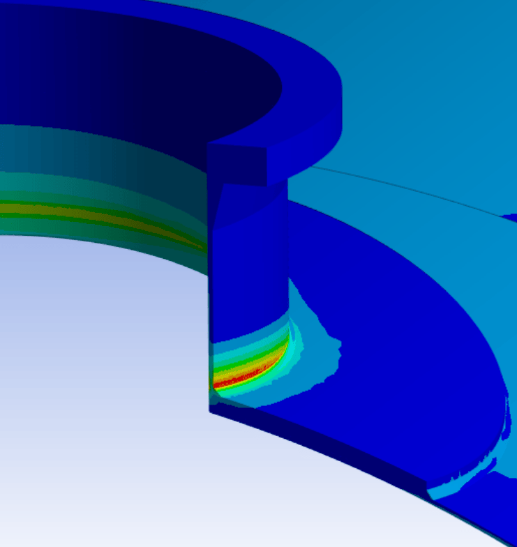
High stresses at weld toe due to nozzle loads.
Stress Concentration Failures
Stress concentration occurs when localized geometry causes stress to increase sharply in a small region. Common causes of stress concentration can include:
- Sharp corners
- Holes and cutouts
- Weld toes and transitions
- Sudden thickness changes
- Nozzle attachments on vessels
In FEA stress analysis, these areas show up as localized “hot spots.” Rather than relying on average stress values, engineers can visualize how load flows through the structure and identify localized failure risk, compare radiused and sharp designs, evaluate weld geometry effects and optimize reinforcement.
Many cracks originate at stress concentrations. Finite element analysis helps eliminate them before fabrication.
Buckling and Structural Instability
Buckling is not a simple collapse. It’s a sudden instability caused by compressive forces that often occurs in:
- Slender columns
- Piping systems
- Pressure vessels
- Tall supports
Traditional hand calculations may estimate critical load, but real-world geometry, boundary conditions and imperfections complicate the picture.
FEA buckling analysis evaluates linear buckling and nonlinear post-buckling behavior, load multipliers and sensitivity to imperfections. Buckling analysis with FEA reveals how close a system is to instability and whether reinforcement or design modification is needed.
Fatigue and Cyclic Load Failures
Components can fail at stresses well below yield strength if subjected to repeated cycles. Common sources of fatigue include:
- Vibration
- Pressure cycling
- Thermal cycling
- Startup/shutdown operations
FEA stress analysis identifies stress amplitude and local hot spots where fatigue cracks are likely to initiate. For fatigue failure prediction, finite element analysis results are combined with fatigue models to estimate life under cyclic loading. This is critical in equipment that experiences thousands or millions of load cycles over its lifespan.
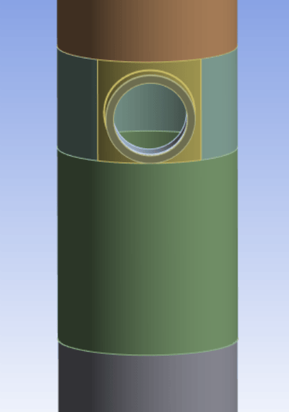
Load applied to vessel nozzle: Undeformed shape

Load applied to vessel nozzle: Deformed shape from nozzle loads
Contact Deformation and Wear
Contact deformation is one of the most under-discussed but critical failure modes. It occurs where components like flanges, seals and structural supports press against each other.
Loads also transfer through small contact areas, creating nonlinear stress behavior. With contact deformation FEA, engineers can model:
- Load transfer between surfaces
- Friction effects
- Localized yielding
- Surface pressure distribution
FEA of contact deformation is essential when evaluating sealing surfaces, bolted joints or support interfaces where improper load transfer can cause leakage, distortion or premature wear.
Thermal and Expansion-Related Failures
Temperature changes create movement. If that movement is restrained, stress develops.
Thermal failures may result from:
- Differential expansion between materials
- Startup and shutdown cycles
- Sustained high-temperature operation
- Creep in pressure components
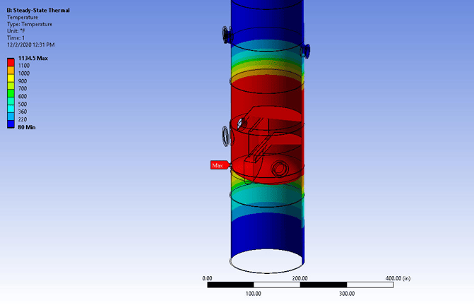
Through thermal stress analysis and finite element thermal modeling, engineers simulate temperature gradients, coupled thermal-structural behavior, transient heating conditions and expansion mismatch. This is particularly important in high-temperature systems and pressure vessels undergoing post-weld heat treatment.

Stresses from differential thermal expansion. Deflected shape also shown.
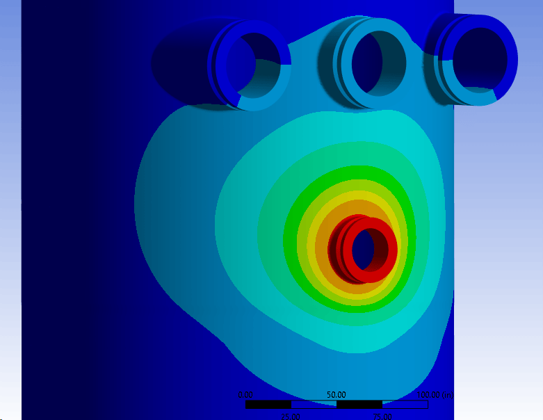
Temperature profile
When FEA Should Be Used in Real Projects
When does it actually make sense to use finite element analysis?
Typical engineering simulation use cases include:
- ASME Section VIII DIV 2 vessel design
- Design validation before fabrication
- Failure investigation after an incident
- Retrofit and reinforcement planning
- Risk assessment in brownfield facilities
- Regulatory or client documentation
The applications of finite element analysis are especially valuable in projects where the geometry is complex, the loads are non-standard or the consequences of failure are significant. In larger EPC projects, simulation often supports both safety and decisions about cost optimization.
Finite element analysis doesn’t eliminate risk, but it makes failure visible before it occurs. In engineering, seeing failure early is often the difference between a situation that’s under control and a costly emergency.
Frequently Asked Questions
What Is Finite Element Analysis (FEA)?
Finite element analysis is a numerical method used to predict how structures and components respond to forces, pressure, vibration, heat and other loads.
How Does Finite Element Analysis Work?
Instead of testing a physical prototype to failure, engineers divide a model into small elements and simulate how each behaves under applied conditions. The result is a detailed picture of:
- Stress and strain
- Deflection and deformation
- Temperature distribution
- Vibration response
Most importantly, finite element analysis is a predictive tool that identifies potential failure before a component is built or modified.
Why is FEA Used for Failure Prediction?
Real-world failure is expensive.
When predicting mechanical failure with FEA, engineers can evaluate:
- Design-stage performance before fabrication
- Modifications in brownfield facilities
- Custom or one-off equipment
- Non-standard loading conditions
Unlike simplified hand calculations, finite element analysis allows detailed engineering failure prediction in complex geometries and load combinations. This is especially valuable when a shutdown window is short, replacing equipment is costly or failure could cause safety or regulatory consequences.
